Alfa Romeo Tech Tips

The following is a list I made for myself to use when removing and reinstalling my 1967 GTV’s 2L motor.  While it is specific to my car, which has many custom pieces, this list may serve as a starting point for you.  Note that I don’t have heater lines to remove, because mine were taken off in 1983 to make the engine bay less cluttered (California delete option).  I also moved the fuse block inside the car, under the passenger side of the dash. 

Before dismantling anything, put the motor on TDC  (P) — with cam lobes pointed out and distributor rotor pointing to cylinder #1. This makes life easier if you’re going to remove the head or even if you plan to remove the timing chain.  The rotor moves in a clockwise direction, in this order: 1, 3, 4, 2.  Depending on how the oil pump was indexed when installed, your rotor may point in a different direction than my car when it is aimed at #1 .  The key is to have the cylinder #1 cam lobes pointed out and the distributor rotor on cylinder #1, when the engine is on TDC (P).   Check the your plug wires as they fit into the distributor cap, beginning with #1, and proceeding around the clock to 3, 4 and 2.  On my car, the rotor is aimed down on #1 (6 o’clock).
Take pictures of wiring before removing any to aid reinstall process
Take off the good lifting bracket and put on the old, scratched bracket
Remove hood
Remove front sway bar
Drop one side of steering center link
Disconnect and remove battery
Drain sump
Drain radiator
Remove radiator thermostat sensor from radiator (I have an electric fan)
Detach wires from radiator fan (one slip-on and on ground to same post as battery ground)
Remove radiator

Passenger side of engine
Remove spark plug wires and distributor cap
Disconnect oil temp and oil pressure wires
Disconnect fuel line and linkage to carbs (when reassembling, don’t forget to attach the carb to block ground)
Remove  carbs (easier to get motor in and out – my carbs are attached to long aluminum mounts)
Remember to reinstall the ground strap from rear carb to block.
Disconnect wires from coil to distributor  (note which goes where – a photo helps those of us with aging brains)
Detach oil vapor line from cam cover & remove vapor canister
Detach vacuum line at rear of engine
Disconnect wires from starter, after first noting what goes where
Disconnect bolts that hold motor mount to frame
Remove bolts to tranny, which removes starter (be careful to note which is the starter shoulder bolt and remember which bolts are longer, which have nuts on end)  When reassembling, don’t forget to reattach the block to frame ground.

Driver side of block
Unhook wires to alternator (one main and one slip-on for ammeter warning light)
Remove alternator (not necessary, but makes life easier)
Disconnect bolts that hold motor mount to frame
Remove good engine lifting bracket from cylinder head and replace with old one (to keep the good one from getting scratched)
From under car, remove as much of exhaust system as necessary to disconnect it from the exhaust header.  (My header won’t come off until the engine is lifted slightly off its mounts.  Installation also requires the engine to be lifted slightly. It also helps on my car if I have have an assistant under the car to slide the header tube into the exhaust pipe)
Remove the lock nuts from the exhaust header with 10mm small socket set and end wrench.  Leave header on the studs until the engine is lifted slightly, so there’s room to pull it off. (Custom header)
Put at least 4” of wood block spacers under the two front tires, to lift the car enough so the engine hoist feet will slide under the car
With rear of car on ground, engine should lift right out using a standard portable hoist

Engine install notes
On my block, there is one sensor on  driver’s side near bottom of engine that is for a 2L car’s warning light.  The sensor is there to fill the hole; it gets no wire)
If the oil dipstick housing was removed after the engine was taken out, reinstall it before the engine goes back in
Lightly grease the transmission pilot shaft
If you’ve used a pilot shaft alignment tool to install your clutch and pressure plate, installation of the motor should not be difficult, though it may take some fiddling to slide the clutch onto the pilot shaft
DO NOT FORGET TO DROP THE STEERING CENTER LINK.  If you don’t, the motor won’t go in and you’ll bend the link trying

After the engine is in
Check that oil drain plug and oil filter are tight
Add engine oil
Put assembly lube on the cam lobes
Fill the cylinder head galleries with oil
Install rear cam cover oil seals with light coating of sealant (Ultra Grey is good)

Quinlisk targa web

© 2008 Jerry Quinlisk. Used with permission.

Setting up your carbs

Dave Andrews has written an absolutely wonderful explanation of how to select the right Weber carbs and how to tune them.  You can read it all here:  Weber Carb Selection and Tuning

He has also created easy to use software.  When you do run it, it will open a window that asks for the size of engine you’re working with.  It also asks at what rpm you make peak power (be realistic), and if you are tuning for power or flexibility.  Then it gives you typical settings you can use as a baseline for setting up your carbs.  When adjusting my new DCOE 45’s, I paid for the assistance of a Weber expert, then put the car on a dyno.  Later, I checked our results against Mr. Andrews’ recommendations and found that the little software program was spot on.

I don’t know if this old DOS program will work on your computer, but I can use it on my Thinkpad.  If you want to give it a try, please send a note to SNO at gwandrw dot com and ask for the jetting software.  I tried to make it downloadable.  Unfortunately, because it’s an exe file, Norton and other anti-virus software blocked my page and labeled me a threat.

Cylinder Head Repair Warning

Below is the illustration Alfa Parts sends out with the 2-liter Victor Reinz head gaskets they sell.  The drawing is used with the permission of Jon Norman, of Alfa Parts.  His number is 1-800-890-2532.  I don’t know if other engine sizes are at risk; that’s a question for Jon.If you don’t understand why this diagram could save you time and money, do a search of the Alfa Digest or AlfaBB.com.

The quick version of the story is this: Older 2-liter motors have oil galleys at the back of the block. Newer 2-liter motors don’t.  Reinz — and some other gasket manufacturers — stopped putting sealant around the oil galley holes, probably when the newer motors came out, and now older engines are at risk of oil and coolant mixing if Jon’s diagram is not followed when installing these head gaskets.

I know this from first-hand experience and have corresponded with several others who’ve suffered the same ugly fate. Alfa Parts was the first company I’m aware of that understood the problem and offered help before their customers found out the hard way.  Jon’s website is:www.alfapartscatalog.com.  I understand from Centerline that now they also offer this advice to Reinz purchasers.The sealant referred to in the diagram is Permatex Ultra Grey.

ultra grey the dark area


Weber carb backing plate; make your own

I did not like the flimsy backing plate that was sold by PiperCross, so I had one cut from a template made from an ITG backing plate.  Mine is slightly modified to fit my 1967 with 2L motor.  If you download my pattern, I suggest you make a paper or card pattern to test the fit on your car before going to the time and expense of creating one out of metal.  I used stainless steel that was cut by a friend’s waterjet machine.

Download an Illustrator ai file here

ram pipes b 72


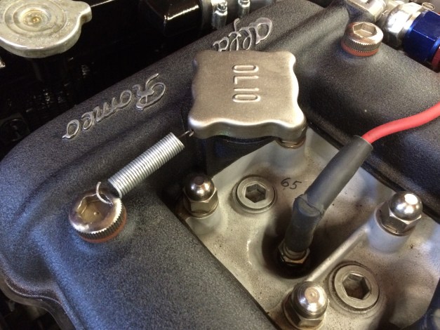
Safety wire (spring) your O170 cap to prevent it from working loose …
Okay, okay. It’s really an Olio cap, if you insist on reading it right side up!

01e31f830930af4a853de44cee5c77acb0ae0e9126

papajam quinlisk web

Who better to preside over anything to do with Alfa technical info than Jim Neill, aka: Papajam? This art is copyrighted by Jerry Quinlisk. May not be used without permission.


Cam Timing

Below are a pair of vintage templates that came with Shankle cams purchased in the early 1980’s. Note the greasy finger smudges. To use them, copy the images to your computer, scale them to accurately match the rulers (try reducing them to 65% of actual for starters), then print them on heavy paper and cut around the black outline. Presto! You’ve got cam timing templates.

 Shankle intake newest Shankle exhaust newest


Valve Shim Adjustment Calculator

Click the link to open an Excel sheet that will help you calculate shim sizes needed to adjust your valves.  I found this fine little tool on AlfaBB, posted there by Paul, aka: 67Coinhole (Don’t ask me what it means, I only report the news).  Paul writes in his post:  “I tried to make it simple and easy to use. It includes a page from the Giulia 1600 Shop Manual and sheets in both mm and inches. After entering your current gaps and shim sizes, you can enter correct gaps to find out the shim sizes you will need, and/or you can enter replacement shim sizes to see what the resulting gaps will be. (Yeah, I know it’s not brain surgery or even a tonsilectomy, but maybe it’ll save someone a little time when they need it.) DISCLAIMER: I MAKE NO CLAIMS OR WARRANTIES AS TO THE ACCURACY OR CORRECTNESS OF THE SPREADSHEET AND ITS CONTENTS AND ACCEPT NO LIABLITY FOR DAMAGES RESULTING FROM ITS USE. USE AT YOUR OWN RISK AND OF COURSE, MEASURE TWICE.”  All I can add is that I used Paul’s calculator and found it handy.   Thanks, Paul!

Click to Download: Valve Shim Calculator